Wednesday, October 27, 2010

Kansas City’s new performing arts center is a showcase of outstanding steel-framed structures


A Kansas City’s new performing arts center is a showcase of outstanding steel-framed structures.
ATOP A HILL with a commanding view to the south and overlooking the revived Crossroads Arts District sits the newest addition to the Kansas City skyline, the Kauffman Center for the Performing Arts. This world-class entertainment venue has proven to be as challenging to design and build as it is expected to be beautiful and functional.
Scheduled to be completed and ready for the 2011 performance season, it will be the performance home for the Kansas City Symphony, the Lyric Opera of Kansas City, and the Kansas City Ballet.
The Kauffman Center, envisioned by Muriel Kauffman of Kansas City as early as 1995, was finally brought to fruition by her daughter Julia Irene Kaufmann. The 285,000-sq.-ft facility consists of the 1,600-seat Helzberg Hall, for symphonic concerts, and the 1,800-seat Muriel Irene McBrien Kauffman Theatre for live stage performances. A third independent structure acts as a shell enveloping the two internal buildings. This unique architectural showpiece starts with a series of segmented vertical arcs forming the north wall and, from the top of the arcs, descends to the south with a gentle sweep ending with its signature cable-supported glass atrium.
A Structural Framing Challenge The complex geometry and intricate connections required to connect the symphony of trusses and rolled beams resulted in hardly a 90° angle or straight piece of steel anywhere in the structure. Working as a subcontractor to J.E. Dunn Construction, Hirschfeld Industries was specifically selected as the structural steel contractor on this unique project because of its history of expertise with complex steel structures and in particular, the detailing, fabrication, and erection of elaborate trusses.
When completed, the structure weighed in at 3,989 tons of steel with 938 tons, or 24% of the total structure, being rolled steel. Rolling was equally split in the hard direction and in the easy direction. The top and bottom chords of the north wall vertical trusses are typically W14r99s and W14r211s rolled the easy way.
The top and bottom chords of the east/west trusses forming the roof of the shell and curved in the horizontal plane are typically
W14r90s rolled the hard way.
The concert hall, located on the east side of the site, consists of six levels of structural steel framing. The roof of this structure comprises six straight east/west trusses with clear spans ranging from 43 ft to 104 ft and an average depth of 14 ft, all supported by the concrete at Level 8. The organ trusses, aptly named for shaping the back wall of the organ chamber and echoing the shape of the outer shell, are located at the north end of the structure and consist of eight curved vertical trusses each approximately 47 ft in height extending from the concrete frame at Level 8 and connecting at the top to one of two trusses.
The second internal building, the proscenium theater, is located on the west side of the site and also consists of six levels of structural steel framing. This structure takes a slightly simpler approach with the roof structure consisting of only four straight east/west trusses with the northernmost truss tied into the concrete stage tower just to the north. A maze of multi-leveled curved catwalks is hung from the trusses.
The massive free-standing lattice shell forming the north wall is composed of 27 vertically curved north/south trusses rising to a height of 139 ft above the ground. Stretching between the top of the trusses and the box truss and defining the extreme south end of the steel structure is a series of W24s and W21s in the same vertical plane of each of the corresponding curved trusses.
Lateral resistance in the north/south direction is provided by six braced frames. Lateral resistance in the east/west direction is also provided by braced frames between the north wall trusses.
        ENLARGE IMAGE       
^
^

A Many of the connections required multiple connection plates at various angles, posing challenges to both the detailer and the fabricator.


Acoustical Issues
Internal noise abatement is a critical consideration for dual-use venues such as this. Throughout the design and construction of the steel framing, careful consideration was given to avoiding the transfer of airborne noise as well as reverberations throughout the structure. The structural steel frames for the concert hall and theater were designed to be completely independent of the surrounding steel and concrete structure. A minimum acoustic joint of 2 in. at ground level, increasing to more than 6 in. at the top of the structure where the wind loads are more significant, was required between the inner buildings and the shell to control both airborne and structure-borne noise from entering the occupied space. Inspections conducted at the end of the erection of each sequence before vacating a specific area ensured that all temporary erection aids had been removed, thus preserving the acoustic isolation.

Detailing Connection Design
Consteel Technical Services, a wholly owned subsidiary of Hirschfeld Industries,  used Tekla Structures, version 11.3, to provide highly accurate and interactive 3D computer modeling. With the structure being predominantly curved with braced frames on radial grid lines, it was by far the most complex and challenging structure the team had detailed. Structural Solutions,
Inc., designed the bolted connections using standard holes, per the erector’s requirement for immediate stability of the member, and slip critical bolts using a Class B faying surface. This resulted in a lower bolt shear capacity than for a bearing condition, so the quantity of bolts and size of the connections increased. However, it was required to eliminate any slippage in the connection and maintain the specified tension in the cable structure connected to the structural steel.
As many as 20 modelers, editors, and checkers were working in the Tekla model at any one time. Difficulties sometimes were encountered in avoiding clashes within the model, although these were not insurmountable problems. Unexpected problems were encountered, however, as the size of the model eventually approached the capacity of the software simply due to the complexity of the geometry. This was resolved by separating the model into two independent models—one for the concert hall and proscenium theater internal buildings and another for the external shell. The separation was done after the overall geometry had been established and shop drawings were being developed for the north wall, so there was little potential for any unknown clashes between the two models. However interface checks between the models still were done on a regular basis. (See sidebar “No More Maxing Out.”)
Throughout the detailing process, close collaboration between the design team, connection engineer, general contractor, and steel fabricator was a necessity in finalizing the structural design. Virtual meetings using online visual and audio links (via “Go to Meeting”) were an essential tool in bringing all parties together to visualize, design, and detail, the complex nodes with massive shear plates converging at different relative angles. As the 3D model was being developed, a detailer was brought in to work face to face with the design team, thereby incorporating the myriad of painting and fireproofing details on the steel as well as the exact location of the shop-attached pourstop. This preplanning was extremely beneficial to all and resulted in minimal field modifications and interruptions.

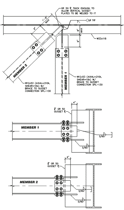
The lateral load resistance system, braced frames, consisted of wide flange diagonals connected to gusset plates with claw angle connections. The axial transfer forces across the joints were accommodated with massive end plate connections, some as long as 11 ft and up to 3 in. thick, with the flanges shopwelded to the end plates. This applied tension to the end plate bolts, reducing their effective clamping force and thus their slip resistance. The connections were carefully designed to ensure the required capacities were achieved, all while allowing for no connection slip at strength-level forces.
The cable supported glass system at the south end of the building introduced significant challenges to the connection design. Due to the high tensile forces required developed by the cable system, significant lateral and vertical loads were imparted into the external shell structure. No connection slip could be permitted in order to ensure the cables maintained their required tensile forces.
The connection design information was provided by the connection engineer to the detailer via connection tables for the simpler connections and intricate AutoCAD sketches for the more complicated joints. As the joint complexity increased, this process became iterative, with the connection engineer and detailer sharing copies of the 3D model until the joints were finally and completely detailed. Before the shop drawings were sent to the design team for approval, the connection engineer reviewed each one to ensure the connection design intent was correctly interpreted. The result was a steel structure of untold complexity erected with very few it-up issues in the field.

Fabrication
Dividing the structure into ten fabrication/erection sequences (one for the concert hall, one for the proscenium theater, and eight for the outer shell) and further subdividing the structure into 54 manageable shipping priorities allowed the construction site to maintain the erection at a productive rate while keeping the staging areas from being inundated with not-yet-needed assemblies.
To accommodate the compressed fabrication schedule, truss fabrication was done mostly in Hirschfeld’s Abilene, Texas, shops with the structural work being conducted in its San Angelo, Texas, shops. Trusses were shop assembled to the greatest extent possible still allowing the shipping of oversized and overweight assemblies to Kansas City via permit.
During crucial fabrication periods, Hirschfeld engaged a detailer to be present in the shops armed with the latest technology - and electronic total station and the industrial measurement software. That enabled extraction of the 3D coordinates from the
Tekla model and their transformation into any plane required to achieve the complex build of the roof steel curved members as well as satisfy the tolerances required during fabrication. This essentially gave the shops the capability of building any achievable shape.
Conversely, the shops could take the as-built subassembly dimensions and transfer the data back into the model to provide actual to theoretical comparisons. This would then allow a simulated trial erection of fully formed truss assemblies before lifting and confirming that the interface with adjoining members worked.

Erection
Not unlike the talent of the performers and the tireless rehearsals needed to create the magnificent sound soon to be found in the Kauffman Center, the construction process of the structure required the absolute best contractor partnerships in the industry to orchestrate every detail. Integral to the preplanning and execution of the erection of the structural steel was the 3D modeling and staged analysis of an elaborate 52-stage erection/stability plan created by the Midwest Steel erection team. Twenty-three drawings, by section, were generated for stability bracing, 14 drawings for rigging of all lifts and seven drawings for crane logistics. Critical to the development of the detailed erection plan was a staged load analysis to maintain stability for the partially erected structure. Secondary construction loads were considered to accommodate the follow-on trades during erection as needed.
There were 26 critical lifts planned and executed on this project.
The connection points at the tops of each building were erected several months prior to the erection of the vertically curved trusses.
Control of the position was critical in order to erect the back of the house and close the structure. Jacking frames were designed to stabilize and maintain geometry of the trusses. The front of the house had a continuous curved box truss that ran from one end of the project to the other connecting the exterior structures of the con-cert hall and the proscenium theater. This was considered the most critical geometry on the project and served as the geometrically critical connection basis to the structure for the cable-supported glass atrium that served as the entire front of the structure.
For each lift a critical lift plan was developed and team meetings were conducted to simulate every detail and to be sure every-one understood their roles in the process. The Tekla model was a critical tool for this project. Within the model, Midwest Steel was able to verify piece weight and geometry, determine the center of gravity of the pick piece and to review the swing path for the piece.
Crane staging was verified in relation to the initial staging position, the final set position and to verify a clear swing path. Lay-down areas were coordinated for pre-assembly, trip and set.
A universal lifting apparatus was designed and modified as detailing progressed. Prior to erection, a practice lift was performed to verify crane capacity using the onboard computer and to make sure the swing path was unobstructed. This was a major concern due to the geometry of the building. There were many levels of concrete and steel to navigate the crane boom and picked piece around in order to set each piece. In addition, step-by-step, bullet point directions were created and used by the crew during the lift which kept everyone focused on safety.
Another factor of expertise was appropriate equipment selection to execute the lifts. Plans were developed that reduced crane movement and lowered the sled weights. These details saved time, eliminated the need for a secondary crane, and resulted in safer execution of the lifts.
The Kauffman Center’s structural steel work was completed in
February 2010. The facility is scheduled to be fully operational for the 2011 performance season. For more information, visit www.kauffmancenter.org.
As with all large undertakings, the development of the Kauffman
Center project has been a collaborative team effort. Jon Vinson, who recently completed his 40th year with Hirschfeld, has been a key player from the inception of this project. He spearheaded the realization of the design as it advanced toward the fabrication stage and deserves a lot of credit for its successful completion.
The author also wishes to thank Tom Broad of Midwest Steel for providing information on the erection methodology.

A Many of the connections required multiple connection plates at various angles, posing challenges to both the detailer and the fabricator.

New Code of Standard Practice for Structural Steel Buildings and Bridges

AISC has released its 2010 Code of Standard Practice for Structural Steel Buildings and Bridges (AISC 303-10). The new edition of the Code reflects industry advancements and provides engineers, owners, architects, general contractors, and others associated with construction in structural steel, with a useful framework for a common understanding of acceptable standards when contracting for structural steel.
Since publishing the first edition of the Code in 1924, AISC has constantly surveyed the structural steel design community and construction industry to determine standard trade practices. Since then, this Code has been updated periodically to reflect new and changing technology and industry practices.
Like the 2005 edition, the 2010 edition is not a complete revision of the  Code but does include important changes and updates. Among the most significant changes in the 2010 Code are improvements in how connection design delegation is handled.
“The significant improvement in Section 3.1.2 is the result of collaboration between the AISC Code Committee and the Council of American Structural Engineers (CASE) Guidelines Committee, ”said Charles J. Carter, AISC vice president and chief structural engineer. “It represents a solution to connection design delegation that the design community and steel construction industry have needed for many decades.”
Based on the deliberations of a fair and balanced committee consisting of structural engineers, architects, a code official, a general contractor, fabricators, a steel detailer, erectors, inspectors, and an attorney, the following modifications have been made in the
2010 revision of the Code:
• The scope in Section 1.1 has been revised to cover buildings and other structures in a manner that is consistent with how buildings and other structures are treated in AISC 360 (the AISC Specification for Structural Steel Buildings). A similar and corresponding revision has been made in Section 1.4.
• The list of documents referenced in Section 1.2 has been editorially updated.
• Section 1.9 has been added to emphasize that not all tolerances are explicitly covered in the  Code, and that tolerances not covered are not to be assumed as zero.
• Clarification has been added in Section 2 that base plates and bearing plates are considered structural steel if they are attached to the structural frame, but not if they are loose items that do not attach to the structural steel frame.
• Editorial improvements have been made in the Commentary to Section 3.1 to improve upon the list of items that should be provided in the contract documents, as well as to link column differential shortening and anticipated deflections to information that has been added in the Commentary to Section 7.13.
• Explicit requirements have been added in Section 3.1.2 as “option 3” for when connection design work is delegated by the Structural Engineer of Record (SER) to be performed by another engineer.
Provisions covering connection design by the SER (option 1) and selection or completion of basic tabular connections by a steel detailer (option 2) also have been revised for consistency with and distinction from option 3. Additionally, the denied term substantiating connection information has been added to the Glossary, and revisions also have been made in Section 4 to correspond with the addition of option 3 in Section 3.1.2.
• Information has been added to the Commentary in Section
4.1 to summarize the importance and benefits of holding a pre-detailing conference to open lines of communication and develop a common understanding about the project.
• Section 4.7 has been added to address requirements for erection drawings.
• Section 6.4.3 has been modified to better address incidental camber in trusses. Information has been added in the
Commentary to Section 7.10.1 to better describe the provisions that relate to special erection conditions or other considerations that are required by the design concept, as well as to highlight special considerations in the erection of cantilevered members.
• The intent in Section 7.13.1.2(d) has been clarified in the text as well as with the relocation of supporting Commentary.
• The intent in Section 10.2.5 has been editorially clarified for groove welds in butt joints and outside corner joints.
• The document has been editorially revised for consistency with current terms and other related documents.
The 2010 Code of Standard Practice is available as a free download PDF at   www.aisc.org/freepubs.

Tuesday, October 26, 2010

Wind Tower Foundations Built Firm and Fast

Photobucket

 WALKERTON, ONT.-BASED concrete contractor MAHCRETE has been building wind tower foundations since 2005, hut its largest project to date Canadian Hvdro’s \Xolf Island Wind Farm in Kingston, Ont. The ‘Xolf Island facility consists of 86 wind towers, each 285 ft from base to huh and each supporting 12 1-ft-long blades. MATTCRETE built the foundations for all 86 towers in only seven months (from September 2008 to March 2009), therefore efficiency and coordinated efforts were critical to the $480-million project’s success.
Each foundation used about 664 cuyds of concrete with a design compressive strength of just over 5000 psi. The mix design included a high slag content that helped control the heat generated by cement hydration and reduce cracking of the massive concrete slabs. But early strength development was important to keep the project on schedule. MA! ICRETE president 1att Jagelewski says, We needed to reach 4061 psi by 21 days to enable folks to set the towers on time.”
The typical foundation is octagonal, about 56 ft across, 6 ft 8 in. thick, and resting on bedrock. Two of the towers were located in areas with sandy soil; their foundations were each
supported by 24 caissons drilled to bedrock. A l7-ft-diarneter concrete cylinder extends about 6 ft above from the center of the octagon, containing anchor bolts to which the tower structure is attached. MATTCRETE designed and fabricated its own steel forms for the foundations, using one
piece of formwork for each side of the octagon. The forms were lifted into place using a crane, then bolted together to create the desired angles and tied back with telescoping adjustable braces.
Once the formwork was in place, MATTCRETE supervised a subcontractor’s installation of steel reinforcement before placing the concrete using two boom pumps.
Properly consolidating the concrete was an important step, ensuring that the foundations were strong and stable enough to support the towers. “You can’t vibrate it too much or the stone sinks,” Jagelewski says, “hut you have to get it around all the rebar and anchor bolts
without leaving voids.”
NIATTCRETE used a variety of vibrating equipment manufactured by Oztec Industries, Port Washington, N.Y., to keep the project moving. Three were Oztec Model GV-SW wheelbarrow units with 5-hp Honda gasoline engines, and another four were Model BP-5O, the vibrator manufacturer’s largest backpack vibrators, with 2 ½ -hp Honda engines. Both of these Oztec per units feature the company’s “speed-up” transmission, which maintains a vibration rate of 10,000 to 12,000 vpm, and both will run for an hour or more on a full tank of gas. With each of these vibrators, crews used 16-ft flexible shafts with 2½ -in.-diameter steel heads. MATTCRETE also kept about a dozen 214 -lip electric vibrators on hand for backup.
Jagelewski says everyone involved with the project was pleased with the efficiency of construction. “There’s a long lead time needed to get the wind towers and turbines—they have to he ordered about a year in advance—so Canadian Hydro was anxious to get them installed as soon as they were available. But everybody was amazed that we could place more than
73,000 cu yds of concrete in less than eight months.”
Photobucket

Saving time in Tall Wall Contruction

AS HEAD DESIGN engineer for TF System, Inc., Jerry Spude both designs insulated concrete forms (ICFs) and oversees their construction on large projects. For the past 15 years, the Green Bay, Wis.-based company has produced ICFs and sold them through its network of distributors. The stay- in-place forms have been used for a wide range of commercial, residential, and institutional buildings.
Unlike most ICF systems, the TF form segments are oriented vertically, which makes them especially well suited for tall walls. The system consists of four main components:
• Panels made of 2½ -in.-thick, highdensity, rigid polystyrene.
• Corner sets made of rigid, recycled
PVC.
• Stud rails available in either rigid, recycled PVC (standard) or 26-gauge galvanized steel.
• C-channels made of 27-gauge galvanized and painted steel.
The vertical orientation is designed to prevent the wall forms from floating and settling, and to provide a dimensionally accurate wall. With no need to glue, tape, or tie components together, assembly is simple and efficient. The basic components form the walls, provide insulation, create a vapor barrier, and serve as convenient and predictable attachment points.
The TF System requires no special concrete mix design beyond a recommendation to use a 4- to 6-in, slump and aggregates of 3/4 in. or smaller, to make sure concrete flows freely around the stud rails. The concrete should he placed in approximately 4 foot lifts.
Contractors typically consolidate concrete in the system using the same techniques as with any other form, though Spude says that TF’s foam panels are sturdier and less prone to blowouts than some lighter-duty residential ICFs.
The company is currently managing Construction of 120, 000-sq. -ft. residence in Highlandville, Mo., that Spude describes as a “modern-day castle” with some walls that are 16 ft tall. To facilitate the consolidation of the lower 8 ft of wall (the first two lifts), the contractor is using a Rehar Shaker, manufactured by Oztec Industries, Port Washington, N.Y. These tall walls contain No. 5 vertical reinforcing bars, 16 in. on center.
To operate, one person attaches the shaker to the top of the bar, centers the bar in the wall cavity, and turns on the shaker while the concrete is placed. The vibration of the rebar serves to eliminate voids and consolidate the concrete, much as the steel or rubber head does when using a conventional pencil vibrator.
“This is our first job using the rebar shaker,” Spude says, “and it’s saving a lot of man-hours and shoulder strain. The crews don’t have to move the vibrator up and down during the pour, so it’s quite a bit easier for them. After the first two lifts, we’re using standard insertion-head vibrators to consolidate the tops of the walls. This method seems well suited for tall concrete wall construction, whether it’s with ICFs or other types of forms.”
Photobucket

With forms braced, crews direct pumped concrete betweem foam panels.


Photobucket

To operate the rebar shaker, one person attaches it on top of the bar, centers the bar in the wall cavity. And turns on the shaker while the concrete is placed.
Photobucket

The TF System Inc.’s vertical ICF design consists of polystyrene foam panels, steel or recycled PVC stud rails, corner sets, and C-channels.

Vibration techniques

Vibrators are easy to operate, although getting good consolidation requires a knowledgeable craftsman. Some European countries actually require vibrator operators to he licensed. Here are few tips to improve consolidation:
• Do not use vibrators to move Concrete horizontally—this can result in separation of the aggregate from the paste (segregation). Vibrators can, however, he used to “melt” a pile of concrete that was placed by bucket or buggy.
• Keep lifts in walls and columns less than 20 inches thick or about the same as the length of the vibrator head.
• The critical questions for the vibrator operator are how far apart to insert the vibrator and how deep to penetrate into the preceding lift.
• Vibrators should he sized and positioned to ensure that all concrete within the forms falls within the radius of influence (see Fig. 1). Use the largest vibrator that will fit between the reinforcement. The center-to- center distance between vibrator insertions should be 1 ½ times the radius of influence of the vibrator.
• Lifts should he placed while the preceding lift is still soft enough to penetrated by the vibrator. If that’s impossible, vibrate near the cold joint hut realize that a lift line will be visible.
• A graphical technique can help to determine how deep to penetrate into the preceding lift. Knowing that the vibration waves slope up at about a 30 degree angle from the tip, place a 30-60-90 triangle at the midpoint between  the insertion points and measure the depth of revibration into the preceding lift and then the total insertion depth (see Fig. 2). Making sure that the boundary between lifts is vibrated will knit together the lifts and eliminate lift lines in the concrete.
• Insert the vibrator as quickly as possible to the proper depth into the previous lift. Typically it will sink under its own weight.
• Hold the vibrator at its maximum depth for S to 1S seconds. Withdraw it at 3 in./second for structural concrete or 2 in./second for architectural concrete (these are the withdrawal rates recommended by AC! 309). Slow withdrawal allows the vibrator to stay below the escaping air forcing it up and out of the concrete.
• Moving the vibrator up and down slightly closes the hole behind the vibrator.
• Make sure the vibrator head remains vertical—don’t force it in at an angle.
• Don’t force the vibrator into congested reinforced concrete because you can end up with a vibrator that is stuck in the reinforcement.
• Proper consolidation is often a judgment call—experienced operators can tell if they are getting good consolidation by the sound of the vibrator.
• Despite all this, if you still have hug holes in the concrete surfaces (after stripping the forms), reduce the distance between insertion points by 20% to 30% below the
standard 1½ times the radius of influence. If there are still some hug holes try spading near form surfaces
• Do not let the vibrator tip contact the form surfaces—this can damage the form panels. Rubber vibrator head tips can help reduce this potential damage.
• After the concrete surface has
stopped bleeding, revibration can he used to remove air pockets in the top lift. Don’t revibrate deeper than about 3 feet and also not with very stiff or harsh mixes.

• For exposed architectural concrete, experiment with vibration techniques to avoid color variations on the surface. For more information, read Guide to Cast-in-Place Architectural Concrete Practice, ACI 303 R-04. 
Photobucket 
FIGURE 1 Use the proper size of vibrator and keep vibrator insertions
at 1 ½ time the radius of influence

Photobucket 
FIGURE 2 A graphical technique can help in determining howdeep the vibrator shoul penetrate into the preceding lift.

Monday, October 25, 2010

Vibrating Self-Consolidating Concrete

By definition, self-consolidating concrete does not require mechanical consolidation. But the problems with SCC are that it is susceptible to segregation, requires more expertise and quality control, can be expensive, and is not always robust (meaning small changes in water content can cause big changes in workability). Even with true SCC (slump flow greater than 18 inches), contractors will sometimes use a little vibration just to make sure the mix is consolidated, especially with congested reinforcing steel. In a properly proportioned mix, this vibration will not lead to separation of the aggregate from the paste (segregation) although there can be some grout leakage at form joints. ‘With slump flows below about 23 inches,” said SCC researcher David Lange, professor at the University of Illinois Champaign, “there may be the need to vibrate just a little bit to help the material move, usually just at the end of the pour when finishing off the top surface.”
The other type of concrete that should be addressed is “high-flow” concrete—this is not quite SCC but is concrete that still flows easily (slump flows between about 14 and 18 inches or even up to 20 inches). This class of concrete is lower priced than 5CC and more robust but still has most of the advantages (rapid placement, fewer workers needed, good finished surfaces). This is a very practical material but it does require some mechanical consolidation (vibration). “If there is access for vibrators then don’t use SCC, but consider “high-flow” concrete,” said Jack Gibbons, technical director for the Concrete Reinforcing Steel Institute, Schaumburg, Ill. “Trump Tower and the Aqua in Chicago are great examples of using 21st century methods without the expense and risk of SCC.”
Photobucket 
Proper consolidation is often a judgment call-experienced operators can tell 
if they are getting good consolidation by the sound of the vibrator

Vibration equipment

Photobucket

The critical questions for the vibrator operator  
 are how far apart to insert the vibrator and 
how deep to penetrate into the preceding lift.

The first decision to make in consolidating concrete is whether to use internal vibration or external vibrators mounted on the outside of the forms.
For this article, we will cover only internal vibration, because that is the most common technique used in the field. External or form vibration is nearly always used in precast plants and sometimes in field applications where the forms arc getting multiple uses and being moved as an assembly (gang forms) from place to place.
Internal vibration equipment is available from a variety of manufacturers although it all works in similar ways:
•Concrete vibrators develop vibration by spinning an eccentric weight within a housing (the vibrator head) typically at a very high speed. This action creates vibrations in the range of 10,000 to 17,000 vibrations per minute.
• Flexible shaft vibrators are the most common type used, where a flexible drive shaft in a housing spins the eccentric weight inside the vibrator head. The core of the flexible shaft is made from high-strength braided steel wire and the casing is steel reinforced rubber. Shafts come in various standard lengths up to about 20 feet long, although shafts can be coupled up to 65 feet.
• The shaft may be driven by an electric motor or by a gasoline or diesel engine. Some power units turn at speeds high enough to develop the required and others must be geared
to achieve the needed speed. There are also pneumatic motors available to drive flexible shaft vibrators.
• Some manufacturers have developed quick connect systems between power units and shafts and between shafts and heads.
• Gas power units often come rigged to he carried like a backpack, freeing a worker from having to hold the power unit in one hand.
• Electric motor-in-head vibrators are also available; in these vibrators a small three-phase induction motor is powered by a heavy electrical cable that also serves as the vibrator handle.
• Pneumatic vibrators are used when compressed air is readily available and when vibrators must run for extended continuous periods, such as in mass concrete. The pneumatic motor is in the vibrator head and tends not to heat up like other vibrator s.
• Radius of influence (or radius of action) is the critical parameter in vibrator selection—this is the distance from the center of the vibrator to the farthest distance where complete consolidation will occur in the concrete. Vibrator heads are rated for radius of influence, although this distance varies with the concrete slump— with high slump mixes it can he double the listed value.
• Vibrator heads come in various shapes, diameters, and lengths.
There is no definitive evidence that one shape works better than another, although some dimpled geometries seem to be more efficient. The head size should be matched to the desired radius of influence and the power unit should he matched to the head size.
• With large headed vibrators and larger power units (as big as about 5.5 hp), the radius of action can he as high as 18 inches. Vibrator heads come with regular steel heads or with urethane (rubber) heads. Rubber heads are required with epoxy- coated rebar, where a standard steel head can chip the epoxy and allow corrosion of the steel. Most DOTs require non-metal vibrator heads with epoxy-coated bars.
• Rubber tips are available for steel heads to protect form panels from damage by vibrator tips.
• Undersized extension cords for electric drive motors can lower a vibrator’s performance and even burn out the motor. For example, a 15 0-ft extension cord powering a 2.25 hp motor should have 8 gage wires.
• Manufacturers have developed rebar vibrators that have proven to effectively consolidate concrete and also grout in reinforced masonry. A study at the University of Tennessee on reinforced masonry showed that rebar vibrators were “an acceptable alternative to conventional pencil vibrators.”


Copyright@2010